![]()
The Cricket Beacon
A detailed description of these steps follows;
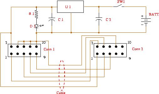
The schematics of the Beacon and the Listenr are given below.
![]()
The Cricket Beacon
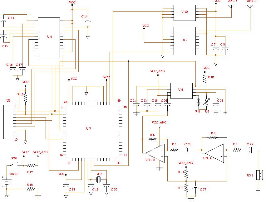
The Cricket Listener
When building Cricket Beacons and Listeners, above schematics should be converted to PCB layouts. There is a large number of commercial PCB design software that can be used for this. We used the PCAD 2000 and CAMtastic 2000 software tools in our design.
We have used two-layer Printed Circuit Boards(PCBs) to implement the Cricket Beacon and the Listener. Folowing figures show both sides of the the Beacon and Listener printed Circuit Boards(PCBs).
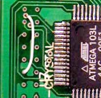
Top side of the Beacon PCB
![]()
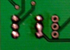
Bottom side of the Beacon PCB
It should be noted that the Beacon PCB contain room for additional components which are not used in the current design.
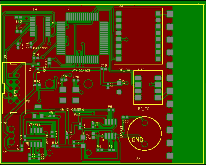
Top side of the Listener PCB
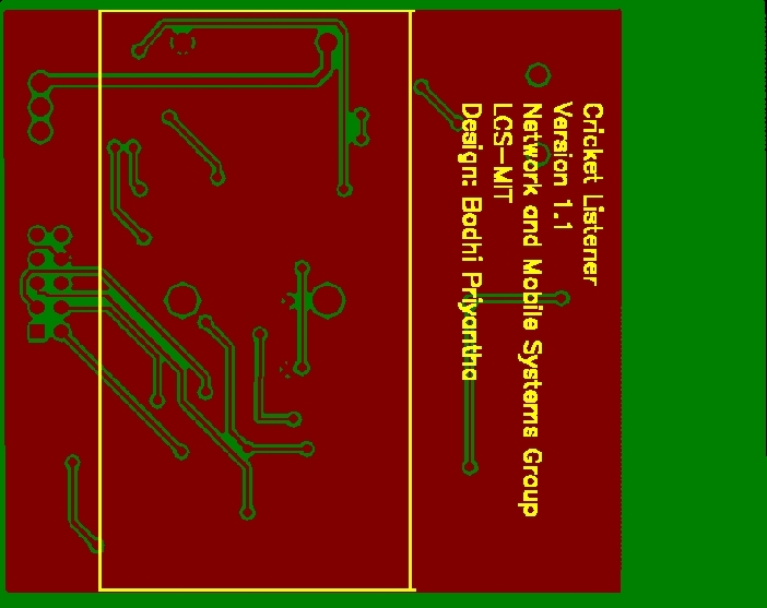
Bottom side of the Listener PCB
The presence of mixed analog and digital circuitry on the listener calls for careful component layout. Some sections of the Cricket Listener PCB are "hand routed" to isolate sensitive analog circuits from digital circuit noise.
You can get above PCBs built by sending the following collections of Gerber CAD files to any PCB manufacturer.
You also need a RS-232 cable connecting the Listener to a host PC. This cable connects the 10-pin cpnnector (U6) on the Listener to a serialport (COM1 or COM2) on the host. Following shows the schematic and a finished cable.
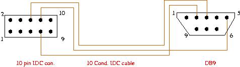
Listener RS-232 cable schematic
First you need to buy the necessary components. Following is the list of components for the Beacon and the list of components for the Listener. These also include distributor part-numbers with links to the corresponding distributor websites. For details about the Atmel processor see http://www.atmel.com/atmel/acrobat/doc0945.pdf
Most of the components used in the design are of "surface mount" type. Soldering these components by hand is a painful and tedious process. You can outsource the fabrication to a commercial organization that does PCB assembly.
Note:-When soldering the beacon, you need to make follwing connections.
To program the microcontrollers on the Listener and the Beacon board, you need to buy the Kanda AVR ISP programming fixture manufactured by Kanda Systems Ltd.. This connects to the Paralle port of a conventional PC and contains its own inbuilt programming device, which is probably powered from the PC parallel port.
This fixture is not directly pin compatible with the Cricket Listener and the Beacon bords. Another cable and a power source must be conneted to the above programmer according to the folowing schematic to enable the programming of the Beacon and Listener boards.
Making the Kanda AVR ISP suitable for programming the Cricket circuit boards.
Here is the list of components for above schematic.
Next you need a compiler to compile the C source code. We used the CodeVisionAVR C compiler for code development. The C laguage used by this compiler has several extensions that make it suitable for programming the micro-controllers.
Follwing is the source files for the Cricket Beacon and the Listener.
The beacon.c code requires an include file named "beacon.h". Here is an example beacon.h file that can be used with becon.c. The beacon.h file can be generated using this Java program. Just compile and run the java program. This will pop up the window given below.
![]()
BeaconInclude pop-up window
For each field in the window, you have to enter the coresponding values and press ENTER. The file "beacon.h" will be generated when you close this window. Following are the meanings and the acceptable values of different fields in the window.
You have to ensure that beacon.h file is located in an include directory of your C compiler.
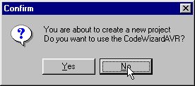
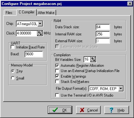
Now to program the Cricket Beacon using the CodevisionAVR C compiler follow the steps given below.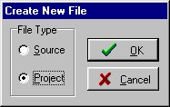
Once fabricated, you need to tune the Listener to detect the 40kHz ultrasonic signal emitted by the Beacon. If you have access to an oscillascope, look at the waveform at pin5 of the IC LMC567CM(U8) w.r.t. to ground (pin4 of the same IC). You should observe a square wave. Now adjust the variable resistor R9 until the frequency of the waveform is 80kHz (or the period is 12.5us). If you do not have access to an oscillascope, you can use an ohm-meter(or a multimeter). First make sure that the listener is switched OFF . Using the ohm-meter, measure the resistance between the pin5 and pin6 of the IC LMC567CM(U8), slowly adjust the variable resistor R9 until the resistance between pins 5 and 6 of U8 becoms 1750ohms.
Under construction. Please contact cricket@lcs.mit.edu.